|
|
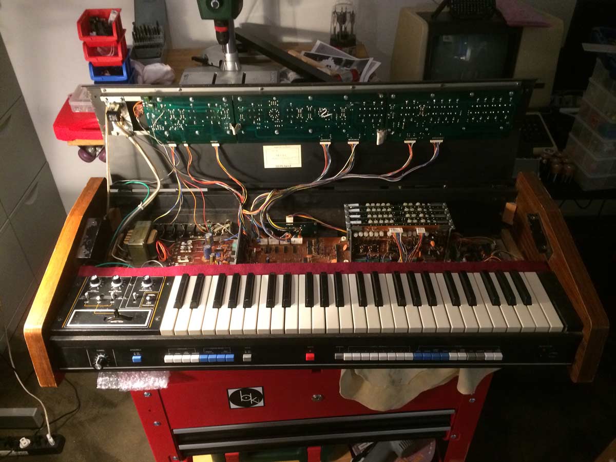
Jupiter-4 Frankenslider Install Notes ================= This is a little bit of commentary to support the photos included here afterwards. Acknowledgements: -=-=-=-=-=-=-=-=- All of this is possible because of a description, BOM and board design from "Homemade Polysynth". This is the link to his description: Polysynth Replacing Roland Jupiter-4 Slider Potentiometer No one, in their right mind, would want Frankensliders in their JP4. Unfortunately, there are no replacement 50K sliders available for the Roland Jupiter-4 and when they fail there is nothing else at the present time. There are seventeen 50K sliders on the JP4. The other 3 are absolutely irreplaceable right now. The irreplaceable ones are ARP RATE, LFO BEND and DELAY TIME. My Jupiter-4 had some greasy, oily goop in all of the right hand sliders. They started to fail last year and then quickly got worse and worse. By the end, there were dead zones in the filter cut off and flaky behaviour with the envelopes. Some previous owner had sprayed some crap into the machine. So I needed to replace all the of 17 50K sliders. I saw Homemade Polysynth's plan and board designs to implement Bourns PTA3043-2010CIB503 50K sliders using 2 daughter boards, pins and spacers. I ordered everything from OSH Park board fab, DigiKey and Mouser. See the "Homemade Polysynth" webpage for ordering data. The photos should be self explanatory. This method works. You will have a working Jupiter-4 with silky smooth sliders again after this. Pay heed to the two issues listed here. Start by building the 17 sliders. Make sure that you get the spacers in the board sandwich as flush as possible. This is not easy. Take your time. After dismantling the JP4 and replacing the sliders there remain 2 issues before you will have a working synth again. First Issue: Major -=-=-=-=-=-=-=--=- - the outer pins of the Roland 50K sliders are connected. These self made stacked ones are not; they make the 2 connections on the bottom and 1 on the top. The upper most is N/C. This is totally fine for 16 of the positions but the VCO LFO MOD slider is connected via the top, not bottom. This problem drove me nuts for hours! When I found it, it was so obvious. (upper means the up direction when facing the opened JP4, looking at the back of the slider boards) Solution: jumper the top pin to the bottom pin Second Issue: Minor -=-=-=-=-=-=-=-=- - the stacking of the potentiometer is meant to level the shoulders of the knob shaft with the originals, this is great as visually, from the outside, the slider caps are all level. The problem is that it is near impossible to get the exact 2.53 mm spacing between boards as solder tends to fatten the pins and push the spacers out a little bit. Also, the tolerances are such that the sliders sit a little bit higher than they should and bash metal. It needs a tiny bit of a spacer to avoid banana'ing the boards when they are fastened again. Solution: I used self adhesive cork about 1.5mm thick along the entire fastening rail. This gives the amount of lift needed. Conclusion: -=-=-=-=-=- My Jupiter-4 works perfectly now. The sliders had been getting worse for a while. There was nothing else I could do but this. Now I can play again. The Bourns sliders are smooth and appropriate to the JP4. I am very grateful to Mr Homemade Polysynth. Download link for photos and this text: -=-=-=-=-=-=-=-=-=-=-=-=-=-=- JP4_Frankensliders.zip Photo Guide: -=-=-=-                         |
|
